|
PARAMETER |
SPECIFICATION |
NOTE |
|
Input |
100~240VAC |
0.2A
50~60Hz |
|
Output |
DC 5V |
1.0 A |
|
DC Jack |
Inside 5V /
Outside
ground |
|
 Requirements
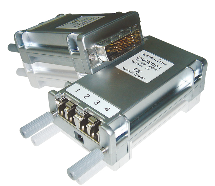
 DVI PC or DVI signal
source (Transmitter)
DVI PC or DVI signal
source (Transmitter)
DVI Monitor or Projector
(Receiver)
100~240VAC 50~60Hz 0.2A
Pseudo
EDID support
There is virtual EDID
data structure in TX
module. This provides
pseudo monitor
information to the host.
Then host can work at
different modes by
reading this data. It
supports all standard
modes such as VGA, SVGA,
XGA, SXGA and UXGA…etc.
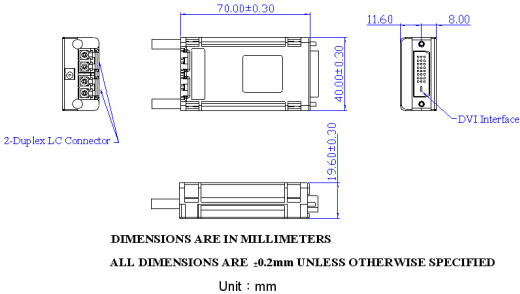
Dimensions
Safety
Regulation
CE and FCC approved.

Installation
Important: Please use
the installation
procedure below.
Improper, or no
operation may result if
the start-up sequence is
not correctly followed.
Step 1:
Carefully unpack the
contents of the shipping
group. Check the
following items:
TX module or RX module
AC/DC Adaptor
Plug converter(Optional)
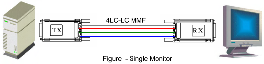
Step 2:
Connect each duplex LC
fiber cable one by one
as indicated number. The
channel “1” of TX
corresponds to channel 1
of RX. The other
channels are the same
connection.
Step
3:
Connect the AC/DC
adapter to the RX
module.
Neglect AC/DC adapter to
the TX module. The PC
may supply voltage
source via DVI
receptacle.
Step 4:
Plug directly the TX
module in the DVI
receptacle of PC. Do NOT
use any intermediate
cable or adapter between
them.
Step 5:
Plug the RX directly
module in the DVI
receptacle of display.
Do NOT use any
intermediate cable or
adapter between them.
Step 6:
Power on the PC and
display.
Note1:The set-up
of screen might be
fitted to the display
resolution. It is
certain to happen such
unfitness if it is first
time to boot up in using
this extender module.
Then, go to Display
Properties in Windows
systems and click the
tap of Settings. Then
you can set the right
display resolution to
meet your display. Once
you set the right
resolution, you could
see displaying the
initial screen at the
same resolution as just
before you powered on.
Note2:You might
not use the AC/DC
adapter at TX module,
but use the power
supplied through a DVI
pin from the graphic
cards. After completing
the installation
instruction, if the
system doesn’t work
properly, you could
re-connect the AC/DC
adapter while all powers
for the system are ON.
Application
Reference

Calculation
of optical power loss
|
Component
Loss |
|
COMPONENT |
LOSS |
SYMBOL |
|
LC connector |
0.3 dB |
 |
|
Single mode
fiber |
0.5 dB / km |
 |
|
Coupler loss
(1X2) |
3.5 dB |
 |
|
Coupler loss
(1X4) |
7.0 dB |
|
Coupler loss
(1X8) |
10.5 dB |
|
Coupler loss
(1X16) |
14.0 dB |
|
Coupler loss
(1X32) |
17.5 dB |
Example
for multiple monitor
installation

For example, we
calculate the power loss
from TX to RX1. In this
optical path, we have 6
connectors, 2.006 km
fiber, one 1× 4 coupler
and one 1× 2 coupler.
If we add all losses in
this, we can get 14.5 dB
in total loss. From the
ordering information on
page 1, we can choose
the model whose power
budget is greater than
14.5 dB for this
installation. For
example, Ace Plus
DVIE005-DVI extender has
15 dB power budget which
is greater than 14.5 dB,
so it can be chosen to
use in this setup.
|
connector
fiber loss
1X4 coupler
1X2 coupler |
0.5 dB 6
pcs
0.5 dB 2
km
7.0 dB
3.5 dB |
=
=
=
= |
3
1
7
3.5 |
dB
dB
dB
dB |
| |
Total loss |
|
14.5 |
dB |